捕获图像-WioTerminal
文档摘要
捕获图像 - Wio Terminal 在本课程的部分中,您将为Wio Terminal添加一个摄像头,并从摄像头捕获图像。 硬件 Wio Terminal需要一个摄像头。 您将使用的摄像头是ArduCam Mini 2MP Plus。这是一款基于OV2640图像传感器的200万像素摄像头。它通过SPI接口进行图像捕捉,并使用I 2 C来配置传感器。 连接摄像头 ArduCam没有Grove接口,而是通过Wio Terminal上的GPIO引脚连接到SPI和I 2 C总线。 任务 - 连接摄像头 连接摄像头。 ArduCam传感器 将ArduCam底部的引脚连接到Wio Terminal的GPIO引脚。
捕获图像 - Wio Terminal
在本课程的部分中,您将为Wio Terminal添加一个摄像头,并从摄像头捕获图像。
硬件
Wio Terminal需要一个摄像头。
您将使用的摄像头是ArduCam Mini 2MP Plus。这是一款基于OV2640图像传感器的200万像素摄像头。它通过SPI接口进行图像捕捉,并使用I2C来配置传感器。
连接摄像头
ArduCam没有Grove接口,而是通过Wio Terminal上的GPIO引脚连接到SPI和I2C总线。
任务 - 连接摄像头
连接摄像头。
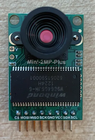
-
将ArduCam底部的引脚连接到Wio Terminal的GPIO引脚。为了更容易找到正确的引脚,请在Wio Terminal周围贴上随附的GPIO引脚标签:
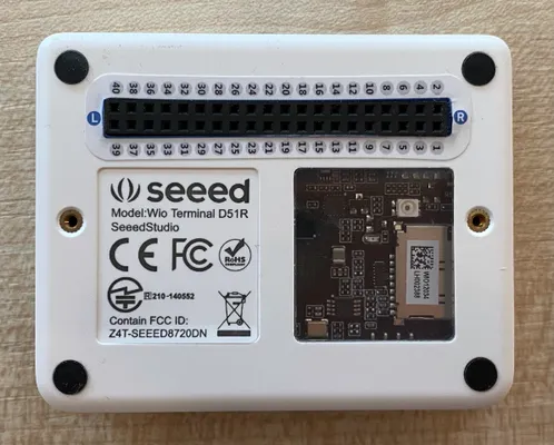
-
使用跳线连接以下引脚:
ArduCAM引脚 Wio Terminal引脚 描述 CS 24 (SPI_CS) SPI片选 MOSI 19 (SPI_MOSI) SPI控制器输出,外围设备输入 MISO 21 (SPI_MISO) SPI控制器输入,外围设备输出 SCK 23 (SPI_SCLK) SPI串行时钟 GND 6 (GND) 地 - 0V VCC 4 (5V) 5V电源供应 SDA 3 (I2C1_SDA) I2C串行数据 SCL 5 (I2C1_SCL) I2C串行时钟 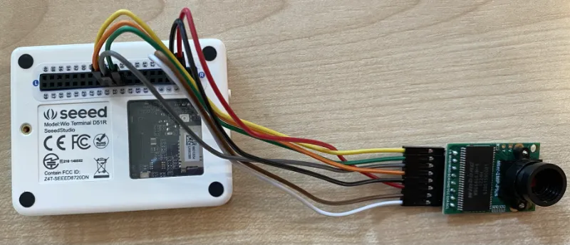
GND和VCC连接提供5V电源给ArduCam。与运行在3V的Grove传感器不同,ArduCam运行在5V。这种电源直接来自USB-C连接器,为设备供电。
对于SPI连接,ArduCam上的引脚标签和代码中的Wio Terminal引脚名称仍然使用旧命名约定。本课程中的说明将使用新命名约定,除非在代码中使用引脚名称。
-
现在可以将Wio Terminal连接到计算机。
编程设备以连接到摄像头
现在可以编程Wio Terminal以使用附加的ArduCAM摄像头。
任务 - 编程设备以连接到摄像头
-
使用PlatformIO创建一个新的Wio Terminal项目,命名为
fruit-quality-detector。在setup函数中添加代码以配置串口。 -
添加代码以连接到WiFi,将您的WiFi凭据放在名为
config.h的文件中。不要忘记将所需的库添加到platformio.ini文件中。 -
ArduCam库不是可以从
platformio.ini文件安装的Arduino库。相反,它需要从其GitHub页面源代码安装。您可以这样做:- 从https://github.com/ArduCAM/Arduino.git克隆仓库
- 访问GitHub上的仓库github.com/ArduCAM/Arduino,然后从Code按钮下载代码为zip文件
-
您只需要此代码中的
ArduCAM文件夹。将整个文件夹复制到项目中的lib文件夹。⚠️ 必须复制整个文件夹,因此代码位于
lib/ArduCam。不要只复制ArduCam文件夹的内容到lib文件夹,而是将整个文件夹复制过来。 -
ArduCam库代码适用于多种类型的摄像头。要使用的摄像头类型是通过编译器标志配置的——这样可以尽可能减小生成库的大小,去除您未使用的摄像头代码。要为OV2640摄像头配置库,在
platformio.ini文件末尾添加以下内容:build_flags = -DARDUCAM_SHIELD_V2 -DOV2640_CAM这设置了2个编译器标志:
ARDUCAM_SHIELD_V2to tell the library the camera is on an Arduino board, known as a shield.OV2640_CAMto tell the library to only include code for the OV2640 camera
-
Add a header file into the
srcfolder calledcamera.h。这将包含与摄像头通信的代码。向此文件添加以下代码:#pragma once #include <ArduCAM.h> #include <Wire.h> class Camera { public: Camera(int format, int image_size) : _arducam(OV2640, PIN_SPI_SS) { _format = format; _image_size = image_size; } bool init() { // Reset the CPLD _arducam.write_reg(0x07, 0x80); delay(100); _arducam.write_reg(0x07, 0x00); delay(100); // Check if the ArduCAM SPI bus is OK _arducam.write_reg(ARDUCHIP_TEST1, 0x55); if (_arducam.read_reg(ARDUCHIP_TEST1) != 0x55) { return false; } // Change MCU mode _arducam.set_mode(MCU2LCD_MODE); uint8_t vid, pid; // Check if the camera module type is OV2640 _arducam.wrSensorReg8_8(0xff, 0x01); _arducam.rdSensorReg8_8(OV2640_CHIPID_HIGH, &vid); _arducam.rdSensorReg8_8(OV2640_CHIPID_LOW, &pid); if ((vid != 0x26) && ((pid != 0x41) || (pid != 0x42))) { return false; } _arducam.set_format(_format); _arducam.InitCAM(); _arducam.OV2640_set_JPEG_size(_image_size); _arducam.OV2640_set_Light_Mode(Auto); _arducam.OV2640_set_Special_effects(Normal); delay(1000); return true; } void startCapture() { _arducam.flush_fifo(); _arducam.clear_fifo_flag(); _arducam.start_capture(); } bool captureReady() { return _arducam.get_bit(ARDUCHIP_TRIG, CAP_DONE_MASK); } bool readImageToBuffer(byte **buffer, uint32_t &buffer_length) { if (!captureReady()) return false; // Get the image file length uint32_t length = _arducam.read_fifo_length(); buffer_length = length; if (length >= MAX_FIFO_SIZE) { return false; } if (length == 0) { return false; } // create the buffer byte *buf = new byte[length]; uint8_t temp = 0, temp_last = 0; int i = 0; uint32_t buffer_pos = 0; bool is_header = false; _arducam.CS_LOW(); _arducam.set_fifo_burst(); while (length--) { temp_last = temp; temp = SPI.transfer(0x00); //Read JPEG data from FIFO if ((temp == 0xD9) && (temp_last == 0xFF)) //If find the end ,break while, { buf[buffer_pos] = temp; buffer_pos++; i++; _arducam.CS_HIGH(); } if (is_header == true) { //Write image data to buffer if not full if (i < 256) { buf[buffer_pos] = temp; buffer_pos++; i++; } else { _arducam.CS_HIGH(); i = 0; buf[buffer_pos] = temp; buffer_pos++; i++; _arducam.CS_LOW(); _arducam.set_fifo_burst(); } } else if ((temp == 0xD8) & (temp_last == 0xFF)) { is_header = true; buf[buffer_pos] = temp_last; buffer_pos++; i++; buf[buffer_pos] = temp; buffer_pos++; i++; } } _arducam.clear_fifo_flag(); _arducam.set_format(_format); _arducam.InitCAM(); _arducam.OV2640_set_JPEG_size(_image_size); // return the buffer *buffer = buf; } private: ArduCAM _arducam; int _format; int _image_size; };这是低级代码,使用ArduCam库配置摄像头,并在需要时使用SPI总线提取图像。此代码非常具体于ArduCam,因此您无需在此时担心其工作原理。
-
在
main.cpp, add the following code beneath the otherinclude语句以包含此新文件并创建相机类的实例:#include "camera.h" Camera camera = Camera(JPEG, OV2640_640x480);这创建了一个
Camera,以JPEG格式保存图像,分辨率为640x480。尽管支持更高的分辨率(最高3280x2464),但图像分类器在较小的图像(227x227)上工作,因此无需捕获和发送更大的图像。 -
在这之后添加以下代码以定义一个设置摄像头的函数:
void setupCamera() { pinMode(PIN_SPI_SS, OUTPUT); digitalWrite(PIN_SPI_SS, HIGH); Wire.begin(); SPI.begin(); if (!camera.init()) { Serial.println("Error setting up the camera!"); } }这个
setupCamerafunction starts by configuring the SPI chip select pin (PIN_SPI_SS)作为高电平,使Wio Terminal成为SPI控制器。然后启动I2C和SPI总线。最后初始化相机类,配置摄像头传感器设置,并确保所有连接都正确。 -
在
setup函数末尾调用此函数:setupCamera(); -
构建并上传此代码,并检查串行监视器的输出。如果看到
Error setting up the camera!,则检查布线以确保所有电缆都正确连接到ArduCam的引脚和Wio Terminal的GPIO引脚,且所有跳线正确就位。
捕获图像
现在可以编程Wio Terminal以在按下按钮时捕获图像。
任务 - 捕获图像
-
微控制器连续运行您的代码,因此在不响应传感器的情况下触发某些事情(如拍照)并不容易。Wio Terminal有按钮,因此可以设置摄像头以通过其中一个按钮触发。在
setup函数末尾添加以下代码以配置C按钮(顶部三个按钮之一,靠近电源开关的那一个)。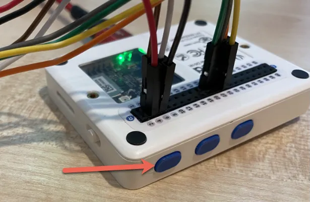
pinMode(WIO_KEY_C, INPUT_PULLUP);在
loop函数中,当按钮被按下时调用此函数:void buttonPressed() { } -
在
loop方法中调用此函数,当按钮被按下时:void loop() { if (digitalRead(WIO_KEY_C) == LOW) { buttonPressed(); delay(2000); } delay(200); }此按键检查按钮是否被按下。如果按下,调用
buttonPressedfunction is called, and the loop delays for 2 seconds. This is to allow time for the button to be released so that a long press isn't registered twice.The button on the Wio Terminal is set to
INPUT_PULLUP, so send a high signal when not pressed, and a low signal when pressed. -
Add the following code to the
buttonPressed函数:camera.startCapture(); while (!camera.captureReady()) delay(100); Serial.println("Image captured"); byte *buffer; uint32_t length; if (camera.readImageToBuffer(&buffer, length)) { Serial.print("Image read to buffer with length "); Serial.println(length); delete(buffer); }此代码通过调用
startCapture. The camera hardware doesn't work by returning the data when you request it, instead you send an instruction to start capturing, and the camera will work in the background to capture the image, convert it to a JPEG, and store it in a local buffer on the camera itself. ThecaptureReadycall then checks to see if the image capture has finished.Once the capture has finished, the image data is copied from the buffer on the camera into a local buffer (array of bytes) with the
readImageToBuffer调用开始摄像头捕获。然后将缓冲区长度发送到串行监视器。 -
构建并上传此代码,并检查串行监视器的输出。每次按下C按钮时,都会捕获一张图像,并在串行监视器上看到图像大小。
Connecting to WiFi.. Connected! Image captured Image read to buffer with length 9224 Image captured Image read to buffer with length 11272不同的图像会有不同的大小。它们被压缩为JPEG格式,给定分辨率的JPEG文件大小取决于图像内容。
您可以在代码-摄像头/wio-terminal文件夹中找到此代码。
您已经成功使用Wio Terminal捕获了图像。
可选 - 使用SD卡验证摄像头图像
查看摄像头捕获的图像最简单的方法是将其写入Wio Terminal中的SD卡,然后在计算机上查看。如果您有一个备用的microSD卡和计算机上的microSD卡插槽或适配器,则可以执行此步骤。
Wio Terminal仅支持最大16GB的microSD卡。如果您有一个更大的SD卡,则它将无法工作。
任务 - 使用SD卡验证摄像头图像
-
使用计算机上的相关应用程序(macOS上的磁盘工具,Windows上的文件资源管理器,或Linux上的命令行工具)将microSD卡格式化为FAT32或exFAT。
-
将microSD卡插入电源开关下方的插槽。确保完全插入直到咔嗒一声并保持在原位,可能需要用指甲或细工具推动。
-
在
main.cpp文件顶部添加以下包含语句:#include "SD/Seeed_SD.h" #include <Seeed_FS.h> -
在
setup函数之前添加以下函数:void setupSDCard() { while (!SD.begin(SDCARD_SS_PIN, SDCARD_SPI)) { Serial.println("SD Card Error"); } }这使用SPI总线配置SD卡。
-
在
setup函数中调用此函数:setupSDCard(); -
在
buttonPressed函数上方添加以下代码:int fileNum = 1; void saveToSDCard(byte *buffer, uint32_t length) { char buff[16]; sprintf(https://www.aiknowledge.cn/images/初学者的IOT开发课程/buff, "%d.webp); fileNum++; File outFile = SD.open(buff, FILE_WRITE ); outFile.write(buffer, length); outFile.close(); Serial.print("Image written to file "); Serial.println(buff); }
https://www.aiknowledge.cn/images/初学者的IOT开发课程/ 这定义了一个全局变量用于文件计数。这用于图像文件名,以便多个图像可以被捕获并具有递增的文件名 - 1.jpg, `2.webp
It then defines the `saveToSDCard` that takes a buffer of byte data, and the length of the buffer. A file name is created using the file count, and the file count is incremented ready for the next file. The binary data from the buffer is then written to the file.
-
Call the
saveToSDCardfunction from thebuttonPressed函数。调用应在缓冲区被删除之前:Serial.print("Image read to buffer with length "); Serial.println(length); saveToSDCard(buffer, length); delete(buffer); -
构建并上传此代码,并检查串行监视器的输出。每次按下C按钮时,都会捕获一张图像并保存到SD卡。
Connecting to WiFi.. Connected! Image captured Image read to buffer with length 16392
https://www.aiknowledge.cn/images/初学者的IOT开发课程/ Image written to file 1.webp
Image captured
Image read to buffer with length 14344
https://www.aiknowledge.cn/images/初学者的IOT开发课程/ Image written to file 2.webp
```
-
关闭microSD卡并弹出它,轻轻推一下然后释放,它会弹出来。可能需要用细工具来做这件事。将microSD卡插入计算机以查看图像。

可能需要几次图像才能调整相机的白平衡。您会注意到图像的颜色变化,前几张图像可能会看起来颜色偏移。您可以通过更改代码在
setup函数中忽略一些图像来绕过这一点。
声明:
本文件灏天文库团队进行了翻译。尽管我们力求准确,但请注意,翻译可能包含错误或不准确之处。原文档以其原始语言为准。我们不对因使用此翻译而产生的任何误解或误译负责。